Wednesday, December 22, 2010

Customizing Your Quick Properties

Good morning every. I will post part 2 of corridor tonight. This morning I will show you how to customize your quick properties. For those of you that don’t use the quick properties I highly recommend you try it a few times. Mine is always on because I like to make changes on the fly. Quick properties make possibly to make quick changes to objects.

When you click on an object, the default properties for that object appears such as style, name, description, and layer. Lets say I want to know more about the object and have the capabilities to make more changes.

1. right click on your quick properties icon on the status bar and select setting.

2. In your drafting settings dialog box change the minimum number of rows from 5 to 15 (Palette behavior) This will allow quick properties to display a number of default rows.

image

3. Select an object such as a C3D pipe structure. Click on the customize button at the top right in the quick properties.   (As you can see my quick properties displays more rows of property information.)

image

4. Here I have the ability to add more property information about my object to the quick properties. If you want to add more objects on your list click on the edit button at the top right  corner of your list. (pencil icon at top)

image

5. The edit object type list dialog box will appear. Here you can select more featured objects you want to ability to show properties for. For example I also added Raster Image, surface, tables, corridors, and block reference. Once you add more feature objects you will have to assign the default property information to appear. Once you are done you can select apply.

image

I personally think using the quick properties will help you save time. One thing I have notice is that if you regular properties dialog box is open and left open, it tends to lag my drawings because every time you select an object it is refreshing or regen while it pulls up the properties of that object. Anyways thank yall for stopping by. Hope yall have a great day.

Tuesday, December 21, 2010

Corridoring a Roundabout Part 1

Hi everyone. So after playing around the intersection feature and roundabouts I came up with many different ways to corridor roundabout. I think we can all agree that every roundabout will unique in its own way. There are many stipulations that influence the design  of the roundabouts, such as traffic flow, ADA, HOA, and drainage flows. Anyways, what I will show yall is just ideas of what you can do to design and corridor your roundabout. Just remember that the more assembly you use to create your corridor, the more memory it will have to use to regen and rebuild you corridor and surface.

PROCEDURES:

1. Create centerline alignments for the left and right side of the roundabout. Begin your alignments at the begin of your PC of your curb returns. Since my main road travels South to North I designed my roundabout alignments to follow the same directions to make it simple.

2010-12-21_0011

2. Now create profiles for both alignments. The beginning and ending elevation will need to match the main roads elevation.

2010-12-21_0012

3. Now we need to create assembles that we can use for this sections. As you can see below, I only used 3 types of assemblies.   (I used 2% cross slopes for my pavement)

2010-12-21_0026

4. Now we need to create 4 polylines that our road section can target to. These 4 polylines need to start and end at the centerline of our main road. These polylines will be the inside/outside edge of pavement for our road, which we will target.

5. Next will build our corridor. Go into your corridor properties and created 2 baselines (Left and right roundabout) For the right side alignment use the roundabout right assembly Then for the left alignment we will used the roundabout left and intersection assemblies.

image

image

As you can see I targeted the polylines.

2010-12-21_01012010-12-21_0100

I didn’t corridor the center of my roundabout because my surface will grade across automatically. (Plus the center is grass)

So that concludes part 1. In Part 2 I will use the intersection feature to corridor the remaining part of the corridor. In Part 3 we will work on the surface editing. Thank you stopping by. Please feel free to make comments or email me.

Sunday, December 19, 2010

AutoCAD WS App for IPhone & IPad

I don’t know everyone knows this but there this an AutoCAD app for a few smartphones. This can come in handy when you need to up a drawing at meeting or site visit. In addition, this can come in handy for a surveyors. I provided helpful links below. As far as I know the IPhone and Ipad are the only applications that support the AutoCAD WS app.

AutoCAD WS
AutoCAD WS Tutorials
ITunes App Store
Civil Engineering Calculation
Autodesk AutoCAD WS
Autodesk - AutoCAD WS

mobile_app

Saturday, December 18, 2010

Christmas Posts

I will be doing a new post every day starting tomorrow till the 1st. This is my xmas gift to all my followers and viewers. Smile

My Website is Now Mobile

Hi everyone. I just wanted to let everyone know that my blog website is now mobile. You can now view my website with most smart phones. I am currently working on a new post for tomorrow that a few of you will be interested in. I won't say what it is yet lol.  I have also added a link for AU mobile below. I have also posted stats from my website which I found very interesting. Anyways I hope everyone is enjoying the weekend and college football bowl mania.

TONYSC3DWORLD MOBILE

AU MOBILE

STATS

TOP 5 Viewed Post

  1. C3D 2011 64 Bit vs C3D 2010 32 Bit
  2. How to Insert Excel Tables With Data Link
  3. Grading Edits Tips and Tricks
  4. 2010 And 2011 Tips of the Day
  5. Storm Sewer Extensions Notes

Thursday, December 9, 2010

User Defined Attributed in Parcel Table

Good evening everyone. Tonight I will show you how to add the custom user define attributed that we created in my previous post into my parcel table. I am more of a visional type of guys so that’s why I attach videos to show every how it’s done. See video below for presentation.

Friday, December 3, 2010

User Defined Attributed in Parcel Table

Good evening everyone. Tonight I will show you how to add the custom user define attributed that we created in my previous post into my parcel table. I am more of a visional type of guys so that’s why I attach videos to show every how it’s done. See video below for presentation.

User Define Attributes for Parcels

Good morning everyone. I hope everyone is having a great week. Well this week I was asked by coworkers on how to add attributes to parcels labels. By using the custom user defined attributed we are able to add items to the parcels such as address, zip code, volume/page, …etc.

STEPS:

  1. Open up your toolspace and select your Settings tab.
  2. Select Parcels
  3. Right click on Unclassified and select new
  4. The New User Defined Property dialog box will appear. Give your new attribute a name such as zip code. The property field type allows you the set the string type such as a number, letters, distance, station…etc.
  5. Hit OK.

 image   image

6.  Now we want to select the parcel label style we wan to revise.

7. Go into your Label style composer  and select the text context where we want to add the new parcel attribute.

image


8. Your Text Component Editor will appear. On your left under the Properties, scroll down to your new zip code attribute and add it to your context  by pressing the right arrow.

image

9. Hit OK and then Apply then OK.  Now to add your new attributes to your parcels, you can use the Multiple Parcel Properties feature. The Edit parcel properties will appear. Here you can add your new attributes and on the right side of your dialog box.

image

I will post another post this weekend on how to add your new user defined attributes to your parcel tables. Thank you for stopping by and have a great weekend.

Tuesday, November 23, 2010

7 Days left before AU starts

If you do not have the opportunity to go to AU this year, you can still experience it online with AU virtual tour. I tried it for the first time last year and it was great. I was able to watch most of the classes live online and also interact with the instructor. Of course  it was such a big hit that now you have to pay for some of those features from last year. Anyways, I’m definitely looking forward to watching some C3D and Map 3D seminars. I have provided a link below for AU virtual webpage.

AU Virtual Tour

Friday, November 19, 2010

Using the Coordinate System Tracker in C3D 2011

Hi everyone. Wow I’m so glad the weekend is finally here. Tonight I would like to show everyone how to use the coordinate system tracker in C3D 2011. This feature can be helpful if you need to see multiple coordinates systems of an object or point. This can come in handy when receiving CAD drawings in a different coordinate system, from clients, contractors or government agencies. See video below or example.

Thursday, November 18, 2010

Using the Mapcheck feature for Boundary

Good evening everyone. Tonight I would like to show everyone how to use the mapcheck feature to check for closure on site boundary. This can be great tool when dealing with survey drawings and plats. I have provide Autodesk help information below about the concept of mapcheck feature.

Use the Mapcheck Analysis command to perform a mapcheck that is based on the precision of the annotation of the label object.

The Mapcheck Analysis command computes mapcheck calculations directly from the selected labels. To perform a mapcheck you must specify a point of beginning (POB) for each parcel. For each segment within the parcel, you select a label containing a direction, direction and distance, distance label, or curve label until the requirements to compute the next vertex of the current segment are met.

As you perform a mapcheck, temporary graphics are displayed in the drawing to indicate the sides that have been entered for each parcel. The current side is displayed in bold indicating origin and direction for that side. The temporary graphics also provide a visual confirmation of possible errors, or indicate that the direction of a line or curve needs to be flipped or reversed.

NoteThe mapcheck report data is stored in the drawing database so you can continue a mapcheck from a previous AutoCAD Civil 3D session. The Mapcheck Analysis window must be open to enable the display of the temporary graphics.


Tuesday, November 16, 2010

C3D 2011 SUPPORT ISSUE

Hi everyone. Well I finally got settled in my new place. Now I can focus more on school, c3d self training and the website. For those of you that have experienced issued with crashing or white background viewcube after installing Service Pack 1, Autodesk has released a simple explanation and solution for the problem. According to Autodesk the problem is because of a bad/old video card driver or video card. It’s best to check for video card  driver updates by going to your into 3DCONFiG options.  See link below for step by step direction to fix the problem.

C3D 2011 Service Pack 1 Problem and Solution

Thursday, November 11, 2010

C3D 2011 Tips

For those of you that are using the new ribbon features for the first time I have attached a short video to help you find your away around things in C3D 2011.

Tuesday, November 9, 2010

November’s C3D Knowledge Base

Good morning every one. Sorry I have not posted in a long while. I have been extremely busy with school, work, softball and finding a new place to live. Anyways, Autodesk has receiver large number of CER for Autodesk 2001 products crashing because of Windows Media Player. The best solution for now is to uninstall Media Player, reboot the OS, then re-install Media Player. See link below.

To change to subject I have started another subdivision design. This has been my 4th in the past 2 years. For those who are having problems with design or lot grading questions please feel free to post or email me. As soon as I get settled in my new place I will be doing several post on several intersection design and lot grading short cuts. Hope yall have a great week.


Knowledge Base

Autodesk Per-incident Support

Wednesday, September 29, 2010

September Knowledge Base and Blogger Day

Good morning everyone. Here is the second half of September’s Knowledge base issues posted by Autodesk. In addition, service pack 1 for 2011 has been release as everyone has heard. On top of that, I attended Blogger Day this past Monday. Autodesk went over some of the new features that were added to 2011 in AutoCAD, Map 3D, and Civil 3D. For those of you that have subscription to C3D and have not downloaded and tried the advantage software, you definitely should.

Autodesk Knowledge Base

Civil 3D 2011 Update 1

Tuesday, September 7, 2010

Disabling Autoload Map3D features

For those of you that don't ever using the Map 3D features and functions  and are looking for ways to save memory, Autodesk just release a post on how to  disable the Map 3D features. See link below.

Disabling Map3D Features

Recovering Drawings

Sorry I haven’t posted in a long while, I have been busy with school. working full time,and still trying to maintain a social life  has left me with little time to do my post.

Anyways, the other day I was working on a large grading drawing for my subdivision I have been working on. After about  2 hrs of working the drawing crashed. I spend the next 1/2 trying to find ways to recover my drawing since I have my automatic save turned off. You may ask why I had my automatic save turned off. Well the grading PG drawings contains many road profiles and many road corridor surface for about 3 miles of road. If I was in the middle of regenerating a surface or corridor and the automatic kicked on at the same time, the drawing would crash. That's something I don't want happening. Anyways, I tried recovering the drawing from the most recent bak file. That didn't work. i tried doing a RECOVERALL and  RECOVER but it kept crashing. I looked to see if I had any temporary backups but I didn't. What I really needed was backup from the previous day or most recent. Well after a few minutes of playing in C3D i ran into this recovery system that Windows creates. I have provide a short video of how I was able to recover a drawing from the most recent windows backup below.

How Windows Creates A Backup: Previous versions are automatically saved as part of a restore point. If system protection is turned on, Windows automatically creates previous versions of files and folders that have been modified since the last restore point was made. Typically, restore points are made once a day. If your disk is partitioned or if you have more than one hard disk on your computer, you need to turn on system protection for the other partitions or disks. Previous versions are also created by Windows Backup when you back up your files.

Monday, August 16, 2010

August Knowledge Base & Support

Here is the August knowledge base issues posted by Autodesk. Majority of the information covers 3d party application problems and solutions. I have posted other important information.

August Knowledge Base

MAPINSERT Hot Fix (C3D 2011)

Raster Design Crashing On Exit (C3D 2011)

32/64 Bit Object Enabler C3D 2011

Graphic Hardware List

C3D 2011 Documentation

O.S. Compatibility for C3D

3 GB Switch

Missing Tool Palettes

C3D 2011 System Requirements

Civil 3D Certification

Save and Qsave Fatal Errors

Undeletable Text

Today I helped a fellow coworker with an issue he was facing and I thought I would share this experience with you.

Well the problem was that there was some notes written with mtext that C3D (2009) would not allow him to delete. C3D would not allow him to click on the text , which acted like the text was not even there. I knew for a fact that I had experience this same issue before in the past. I just couldn't remember what I did to fix it. I have provided below the steps of problem solving I took to solve this issue.

  1. I turned on all the layers = no results
  2. I turned on the wipeout frames = no results
  3. I ran an audit and purge = no results
  4. I turned on the attdisp option = no results
  5. I turned on all image frames = no results
  6. I tried to explode the text = no results
  7. I ran the battman command to see if it was some kind of block issue = no results
  8. I ran –pu and selected all  = no results
  9. I tried the text editor = no results

After trying all these steps, i still could not select the text. I finally decided to tab thru a few of the text commands to see if any of them would ring a bell. TEXTTOFRONT. Once i typed that command I was able to select the text and delete it. After that, i went back to my desk and wrote down the command in my little black book so I would not forget it.  I would like to know how many of you have experienced this same problem?

Anyways be looking for my next post this week and thank you for stopping by.

Thursday, July 22, 2010

July’s Knowledge Base Updates.

Hi everyone. Sorry I haven’t posted in a long while. I have been busy with work and sports. I want to thank everyone that have emailed me questions with issues they have been facing. Anyways I have provided a link for the knowledge base issues posted by Autodesk. In addition, the third service pack for C3D 2010 has been released. If i were you, I would  wait at least a few weeks before installing because there always seems to be problems with the install of new service packs. Anyways , thank you for reading my post.

KNOWLEDGE BASE

C3D 2010 SERVICE PACK 3

Tuesday, June 29, 2010

How to Insert Excel Tables With Data Link

In the last few years I have noticed that some techs and engineers insert drainage and storm tables, created in excel, as PDF files or even do a copy and past into their drawings. I am sure some of you do the paste special option and select AutoCAD entities or Microsoft chart option.


Tonight I will show you another way to insert excel tables with the data link command. If you type the command DATALINK the data link manager will appear. Click on the “Create new excel sheet” and small dialog box will appear asking you for a data link name. I typically provide the project number then the table name such Prop Storm or Ex Storm.


BE SURE TO TURN OFF YOUR PREVIEW
The New Excel Data Link dialog box will appear. You will first browse to your excel sheet. Then select the sheet or tab that you want to use . !. The reason I say this is because it has a tendency to bog down when trying to display your table in a small preview area.


Next select the area that you want to insert.  I have provided a short video presentation on how to insert the able that you just create. The data link command will definitely be a helpful way to add storm and drainage area tables into you plans. I hope this information will be help improve production time.


Monday, June 28, 2010

Part Builder Pt. 1

Hi everyone. Sorry I haven't posted in a while. Softball and flag football season has started so i have been occupied with that and other side projects. Anyways I have received a few emails from some of my followers asking question about part builder, Well tonight I will do my best to try to teach you a few things about part builder. The first step in learning about part builder is knowing the size parameters. I have listed most of the size parameters that you will see.

BdyD1, BdyD2 = These are the diameter dimensions to the circular profile or the body dimension.

Fth = This is the floor thickness.

LenB1, LenB2 = These are the model parameters set to the extrusion or length body

LenA1, LenA2 = These are vertical distances set in the work planes.

SID = This is the inner structure diameter variable and will be set as a list of variables.

Wth = This is the wall thickness variable and can be set as either a constant or list depending on you structure requirements.

SBSD = This is the structure diameter variable and will be set as variable.

PID = This is the pipe inner diameter.

SRS = This is the rim to sump height which based on the auto layout point is the surface insertion point to the bottom of the structure.

SBSH = This is the structure height which is the other component of the vertical control. Remember the difference between SBSH and SRS is the floor thickness (Fth)

Bellow I have posted a short video presentation on how to add size parameter to pipes and structures. I should be able to post Part 2 sometime this week. Have a great week.

Wednesday, June 23, 2010

Support For My Followers

I would like to hear from my followers of issues or problems they are having with C3D 2009-2011. I will do my best to try to answer you question to the best of my abilities. Maybe some of yall are working a design shortcut but just can’t quiet figure it out. Right now I am actually working a presentation on how to corridor a roundabout. If I can’t answer your question I will find someone that is knowledgeable in that area of design or programming. I want to thank everyone that reads my post and those that have made comments and sent me emails. Tonight I will release a post on Part Builder. Have a great week.

Tuesday, June 8, 2010

2010 and 2011 Tips of the Day

Today I'm going to provide you few quick tips and tips how to improve performance with CD3  2010 and 2011.

TIP #1: For those of you that are experiencing  slow zooming and jagged panning when you first install C3D 2010 or 2011 you need to turn off your “Enable hardware acceleration” option. Typically this feature is turned on by default. When I first install both trial version of C3D, I experienced these same effects. After spending a few minutes playing round with setting and browsing through all the feature in the Options dialog box I came across the Enable Hardware Acceleration feature. I decide to turn it off and I immediately noticed a drastic performance boost. You can type “3DCONFIG” to get into your performance tuner dialog box. Select Manual Tune. In the next dialog box uncheck the “Enable Hardware Acceleration”. See images below.


image image

image


TIP #2: For those of you that work with projects that have large aerial images C3D has a feature that allows your make changes to the amount memory C3D used. Here some helpful information: “Civil 3D reserves 25% of the total physical memory (RAM) on your system for inserting images with Raster Extensions. If you increase the default amount, more of the physical memory is used for images and less is available for other operations in Civil 3D and for other applications you might be running.

If you require additional memory for your images, the Civil 3D’s Raster Extension uses a temporary swap file. For example, if you insert a 100 MB file, and the Memory Limit is 8 MB, Civil  3D stores the remaining 92 MB in a temporary file. You can specify where the swap file is created.

You can change the following Raster Extension memory settings:

  • Temporary File Location — The default directory for the temporary swap files is the Windows temp directory.

    Tip For best performance, use a local drive for your temporary swap file. It is recommended that you do not use the drive where the operating system is installed as the drive for the swap file unless this is your only local drive.

  • Memory Limit — Specify the maximum amount of computer memory that AutoCAD Map 3D can use to store image files.

Note The more physical RAM you have, the higher you can make your Memory Limit. The higher the Memory Limit, the less swapping to hard disk occurs and the faster your images load and display. However, do not allocate all available physical RAM because doing so slows overall performance.
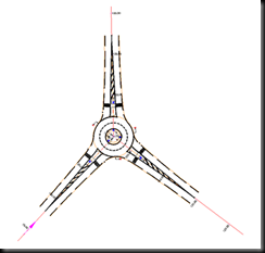
Note Close and restart Civil 3D after adjusting these settings.”

You can make the changes to the memory by either typing “MAPIOPTIONS” command or changing your workspace to Tool-based Geospatial. Then select the Insert contextual Tab. Click the small arrow at the bottom of  the Image Ribbon. This will bring up the


image


image

Note: If you have drawings with large aerials or images that are not being used but need to stay in the drawing , its best to hide the image for faster performance. You can either type the “HIDEOBJECT” command or click on the yellow light bulb at the bottom right corner of C3D.

2010-06-08_2224


TIP #3: If you ever need to know who has a certain drawing open you can use the “WHOHAS” command. Once you type the command the Drawing Open Query dialog box will appear. Just select a drawing file and if the drawing is in use by a user, a dialog box will appear like the image below.

image

TIP #4: I don't know how many people know this but you can use the featureline Insert PI feature for polylines, parcels, survey figures and 3D polylines. I use this feature on a daily basis.

2010-06-08_2232

Friday, June 4, 2010

AutoCAD Raster Design 2011 Object Enabler

I have provided a link for the 2011 object enabler from the Autodesk website.

Raster Design 2011 Object Enabler

New Knowledge Base Issues

I have listed below some of the new issues fixed by Autodesk for this month. Click on the link below for more information.

  1. System Requirements for the Autodesk Network License Manager
  2. Enabling 3GB switch on Windows Vista or Windows 7
  3. Windows 7 support for Autodesk 2010 products

KNOWLEDGE BASE SUPPORT

Thursday, May 27, 2010

Roundabout Design Part 1

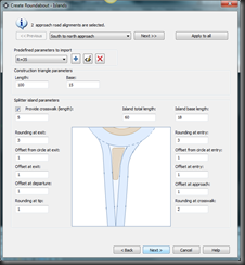
Roundabout and traffic circles are a common form of intersection control used throughout the world and are becoming more and more popular in the United Stated. Civil 3D 2010 was the first to introduce the roundabout feature as a subscription download. The new Civil 3D 2011 has added the roundabout feature to the Home contextual tab under the create design ribbon. The new roundabout feature allows you to create and edit a 2D roundabouts design. The 2D roundabout feature commands can produce roundabout central areas, approach roads, slip lanes, and pavement marking and signage. When you create a roundabout, it automatically created a group of new alignments and polylines that represent roundabout components. Two important items to look for when designing your roundabout is approach lane curb return overlaps and editing the roundabouts.  Roundabouts created using the Create Roundabout command can only be edited in versions of AutoCAD Civil 3D that contain the roundabout creation functionality. I have provided images and A short video presentation on how to create a basic roundabout.
Corridoring a roundabout can be a little confusing and tricky. I just recently designed and corridored two roundabouts in a subdivision I was working on. To save time, I corridored the roundabout with a few profiles and feature lines. You can use the intersection feature but you could be looking at very complex corridor and subassemblies. In part 2 of my post on roundabout, I will show you a few shortcuts on corridoring a roundabout. Please feel free to make comments or email me if you have question.

ROUNDABOUT ARTICLE

CE NEWS


Roundabout Design Part 1

Roundabout and traffic circles are a common form of intersection control used throughout the world and are becoming more and more popular in the United Stated. Civil 3D 2010 was the first to introduce the roundabout feature as a subscription download. The new Civil 3D 2011 has added the roundabout feature to the Home contextual tab under the create design ribbon. The new roundabout feature allows you to create and edit a 2D roundabouts design. The 2D roundabout feature commands can produce roundabout central areas, approach roads, slip lanes, and pavement marking and signage. When you create a roundabout, it automatically created a group of new alignments and polylines that represent roundabout components. Two important items to look for when designing your roundabout is approach lane curb return overlaps and editing the roundabouts.  Roundabouts created using the Create Roundabout command can only be edited in versions of AutoCAD Civil 3D that contain the roundabout creation functionality. I have provided images and A short video presentation on how to create a basic roundabout.
Corridoring a roundabout can be a little confusing and tricky. I just recently designed and corridored two roundabouts in a subdivision I was working on. To save time, I corridored the roundabout with a few profiles and feature lines. You can use the intersection feature but you could be looking at very complex corridor and subassemblies. In part 2 of my post on roundabout, I will show you how a few shortcuts on corridoring a roundabout. Please feel free to make comments or email me if you have question.
ROUNDABOUT ARTICLE
CE NEWS

roundabout_5-27-2010 
image 
image
image image

Tuesday, May 25, 2010

MAY’S CIVIL 3D KNOWLEDGE BASE

i have provide a list of Autodesk answers to a few issues some of us are facing such as blue screens with Nvidia graphic video cards, splash screen closing and targeting specific surfaces.

KNOWLEDGE BASE

Sunday, May 23, 2010

CE NEWS SURVEY

I was reading my CE News magazine for March and I came upon a very interesting article. Here is what the article states “ Shortly after President Obama signed the American Recovery and Reinvestment Act (ARRA) in February 2009, CE NEWS surveyed it’s readers to gauge their attitudes on the prospects for the AEC industry in general and for their firms in particular.” I have provided some of the questions CE NEWS asked and what their readers responses were. I would like to hear your thoughts and response to these questions and how the economy has effected your firm.

CE NEWS MARCH 2010

1. Do you anticipate that the AEC industry will grow, shrink, or remain the same in the next year?

2.  How do you anticipate your firm’s total revenue for engineering services in the next year will compare with the prior year?

3. What is the greatest challenge your firm faces in the coming year?

4. Have you experienced any of the following at your firm during the last 6 months?

ce_news

Thursday, May 6, 2010

C3D 2011 CROP SURFACE

The crop surface feature will come in handy when you have a small project site and you are using USGS contours or aerial contour that covers hundreds of acres. The crop surface feature will allow you to cut area of surface that you need for your project without affect the original surface or source surface. I’m sure some of you are asking why not use boundary and data reference the surface out. Well to answer that question, as far as I know you can not make revision or changes to the data reference surface once you insert it into your drawing. With the crop surface feature you will be able to add points, breaklines, contours…etc. Anyways, this feature would have definitely helped me in my subdivision design I was working on which had 500 acre surface. I have provided a short video below  on how to use the crop surface feature. Remember if you make changes to the original surface and want those changes to reflect to the copied surface, simply select rebuild snapshot then rebuild surface on the copied surface.

.

Tuesday, May 4, 2010

C3D 2011 Other New Features Pt 2

Tonight I played around a little more with C3D 2011 and discovered more new features that I want to share with you.

  1. Crop Surface has been added into the Surface ribbon. This feature allows you to crop an area of surface and export into another drawing or a new drawing. This will come in hand why you have an over USGS surface cover several hundred acres and you only need a small portion of the surface for your site. One rule of thumb, if you make changes to the source drawing be sure to save the current drawing before you rebuild the surface which you just created.

image  image

2. Create Best Fit Profile has been added to the Create Design ribbon under the Home contextual tab. This feature helps  guide you in you design for the best possible and logical path through a series of surfaces profiles and featurelines and other AutoCAD entities.

image   best_fit_profile


3. Application Status Bar has a new look with some new features. First, quick access to your hardware acceleration feature. The 3d orbit, pan, show motion and steering wheel have been removed and added to a floating toolbar on the right side if your screen. A quick to your data shortcut reference has been added. Last but not least, the  Autodesk TrustedDWG link was added which can be used with your TrueView software. 

tool_bar

image


4. Two new features were added to the Ground Data Ribbon. You can now use the minimum distance between surfaces feature. In addition, the resolve crossing breakline feature. This feature will help when you have several breaklines in a EG or PG surface.

image


5. Stage Storage feature has been added to the Design ribbon under the Analyze contextual tab. In 2010 this feature was only available to subscription owners as a download.

image image